Cathode Ray Oscilloscope:
The cathode Ray Oscilloscope or mostly called as CRO is an electronic device used for giving the visual indication of a signal waveform.
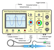
CRO is widely used for trouble shooting radio and television receivers as well as for laboratory research and design.
Using a CRO, the wave shapes of alternating currents and voltages can be studied. It can also be used for measuring voltage, current, power, frequency and phase shift. Different types of oscilloscopes are available in the market for various purposes.
Block Diagram of CRO (Cathode Ray Oscilloscope):
The figure below shows the block diagram of a general purpose CRO .

As we can see from the above figure above, a CRO employs a cathode ray tube ( CRT) ,which acts as the heart of the oscilloscope.
In an oscilloscope, the CRT generates the electron beam which are accelerated to a high velocity and brought to focus on a fluorescent screen. This screen produces a visible spot where the electron beam strikes it. By deflecting the beam over the screen in response to the electrical signal, the electrons can be made to act as an electrical pencil of light which produces a spot of light wherever it strikes.
For accomplishing these tasks various electrical signals and voltages are needed, which are provided by the power supply circuit of the oscilloscope.
Low voltage supply is required for the heater of the electron gun to generate the electron beam and high voltage is required for the cathode ray tube to accelerate the beam. Normal voltage supply is required for other control units of the oscilloscope.
Horizontal and vertical deflection plates are fitted between the electron gun and the screen so that these can deflect the beam according to the input signal.
To deflect the electron beam on the screen in horizontal direction i.e. X-axis with constant time-dependent rate, a time base generator is provided in the oscilloscope.
The signal to be viewed is supplied to the vertical deflection plate through the vertical amplifier, so that it can amplify the signal to a level that will provide usable deflection of the electron beam.
As the electron beam is deflected in X-axis as well as Y-axis, a triggering circuit is provided for synchronising these two types of deflections so that horizontal deflection starts at the same point of the input vertical signal each time it sweeps.
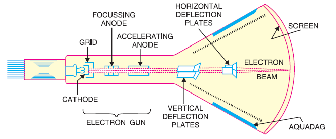
Since CRT is the heart of the oscilloscope, we are going to discuss its various components in detail.
Cathode Ray Tube:
The cathode ray tube or CRT is a vacuum tube of special geometrical shape which converts an electrical signal into a visual one.
A CRT makes available a large number of electrons which are accelerated to high velocity and are brought to focus on a fluorescent screen where it produces a spot when strikes it. The electron beam is deflected during its journey in response to the applied electrical signal. As a result, the electrical signal waveform is displayed visually.
The figure below shows various parts of a cathode ray tube (CRT) .