What is Diode Clipper?
The Diode Clipper, also known as a Diode Limiter, is a wave shaping circuit that takes an input waveform and clips or cuts off its top half, bottom half or both halves together.
Types of Clipper Circuit:
The clipper circuits are of the following types.
1. Series positive clipper
2. Series negative clipper
3. Shunt or parallel clipper
4. Shunt or parallel positive negative
5. Clipper Dual (combination)Diode clipper
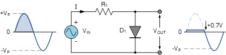
SERIES POSITIVE CLIPPER:
In a series positive clipper, a diode is connected in series with the output, as shown in Fig 1. During the positive half of the input voltage, the terminal A is positive with respect to B. This reverse biases the diode and it acts as an open switch Therefore all the applied voltage drops across the diode and none across the resistor As a result of this there is no output voltage during the positive half cycle of the input voltage.
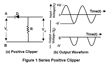
During the negative half-cycle of the input voltage the terminal B is positive with respect to A. Therefore it forward biases the diode and it acts as a closed switch. Thus there is on voltage drop across diode during the negative half cycle of the input voltage. All the input voltage is dropped across the resistor as shown in the output wave- form.
SERIESPOSITIVE CLIPPER WITH BIAS:
Sometimes it is desired to remove a Small portion of positive or opposite half cycle of the signal voltage (input signal). For this purpose, a biased clipper is used Fig 2 shows the circuit of a biased series positive clipper.
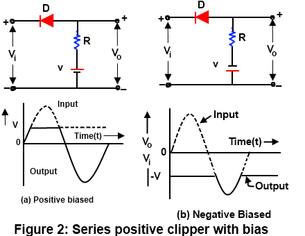
It may be observed that the clipping takes place during the positive cycle only when the input voltage
is greater thence battery voltage (i.e. V > V ). The clipping level can be shifted up or down by varying
the bias voltage (V )
SERIES NEGATIVE CLIPPER:
In a series negative clipper a diode is connected in a direction appositive to that of a positive clipper Fig 3 shows the circuit of a negative clipper.
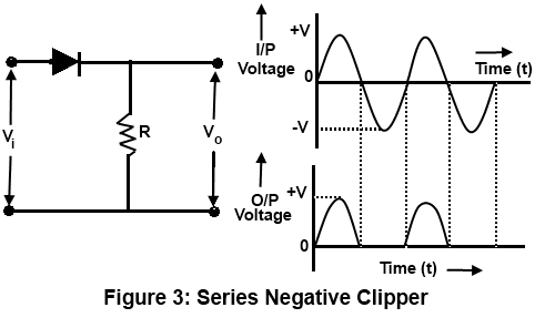
During the positive half cycle pf the voltage, the terminal A is positive with respect to the terminal B There for the diode is forward biased and it acts it as a closed switch As a result ,all the input voltage appears across the resistor as shown in Fig 3(b). During the negative half cycle of the input voltage, the terminal B is positive with respect to the terminal A. Therefore the diode is reverse biased and it acts as an open switch, Thus there is no voltage drop across the resistor during the negative half cycle as shown in the output waveform.
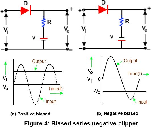
SERIESNEGATIVE CLIPPER WITH BIAS:
Fig 4 shows the circuit of a biased series negative diver. In this circuit clipping take place during the negative half cycle only when the input voltage V > V she clipping level can be shifted up or down by varying the bias voltage ( V)
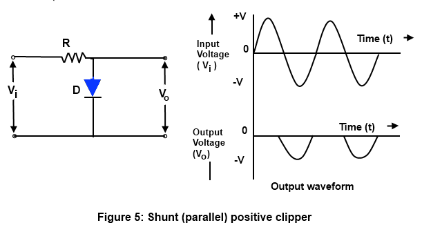
SHUNT OR PARALLEL POSITIVE CLIPPER:
A parallel clipper circuit uses the same diode theory and circuit operation a resistor and diode are connected in series with the input signal and the output signal is developed across the diode. The output is in parallel with the diode hence the circuit name parallel clipper the parallel clipper can limit either the positive or negative alternation of the input signal Fig 5 shows the circuit of a shunt positive clipper In this circuit. The diode acts as a closed switch when the input voltage is positive (i.e. V > 0 and as an open switch when the input voltage is negative (i.e. V < 0) the output waveform is the same as that of a series positive clipper in the parallel clippers the alp will develop when the diode is cut off.
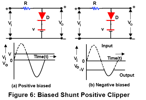
SHUNT OR PARALLEL POSITIVE CLIPPER WITH BIAS:
As is in Fig 6 , positive terminal of the battery is connected to the cathode of the diode. This causes the diode to be reversed biased at all times except when the input signal is more positive the bias voltage(i e V > V ). it will be interesting to know that if the polarity of the bias voltage is reversed, the resulting circuits will be as shown in Fig 6. Here the input signal lying above the voltage —V is clipped the waveforms of the of the output voltage are also shown with figures
SHUNT OR PARALLEL NEGATIVE CLIPPER:
The negative clipper has allowed to pass the positive half cycle of the input voltage and clipped the negative half cycle completely Fig 7 shows the shunt (parallel) negative clipper.
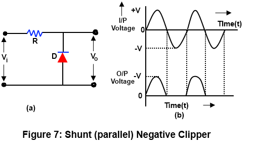
In such a circuit the diode acts as a closed switch for a negative input voltage (i.e. V < O) and as an open switch for a positive input voltage (i.e. V O) the output waveform of the Circuit is the same as that of series negative clipper.
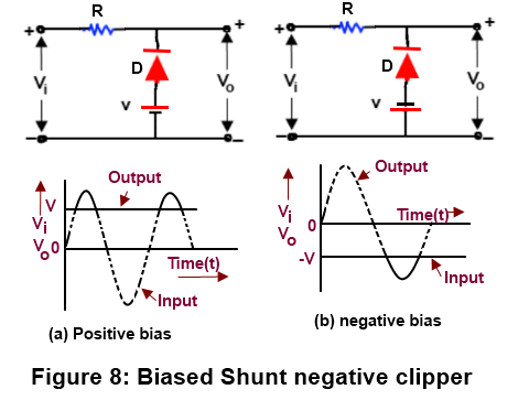
SHUNT OR PARALLEL NEGATIVE CLIPPER WITH BIAS:
In such a circuit clipping take place during the negative half cycle only when the input voltage (V < V ) the clipping level can be shifted up or down by varying the bias voltage (—V ). It will be interesting to know that if the polarity of the bias voltage is reversed, then the resulting circuits will be as shown in Fig 8. Here the entire signal below the voltage level VII has been clipped off .
DUAL (COMBINATION) DIODE CLIPPER:
The type of clipper combines a parallel negative clipper with negative bias (D and B ) and a parallel positive bias (D and B ). Hence the combination of a biased positive clipper and a biased negative clipper is called combination or dual diode clipper. Such a clipper circuit can clip at both two independent levels depending upon the bias voltages. Fig 9(a) show the circuit of a dual (combination) clipper.
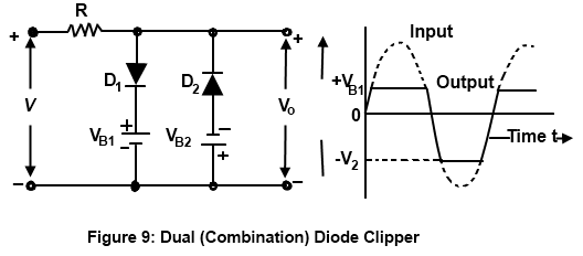
Let us suppose a sinusoidal AC voltage is applied at the input terminals of the circuit. Then during the positive half cycle, the diode D is forward biased, while diode D is reverse. biased. Therefore the diode D will conduct and will act as a short circuit. On the other hand, diode D will act as an open circuit. However, the value of output voltage cannot exceed the voltage level of V as Shown in Fig 9.
