What is a Multimeter?
A multimeter or Volt-Ohm meter, is a device used to measure voltage, current and resistance. Multimeter might be analog type multimeters or digital multimeters, depending on the type of circuit being used. Normally, these hand-held devices are very useful to detect faults or provide field measurements at a high degree of accuracy.
Apart from that, these digital multimeters perform many additional measurements by using digital and logic technology. These may include temperature, frequency, continuity, capacitance etc. The new improved integrated circuits of digital multimeter are more efficient, faster and work with a large accuracy as compared to an analogue multimeter. But in the case of additional features, it is not accurate but close to the reading. A good multimeter is that has continuity and packed with smart features, including the ability to log and graph data and great for troubleshooting.
Features of Digital Multimeter:
Digital multimeter are most advanced instruments that make use of modern Integrated circuits for making measurements. Some of its features which make it famous in the eyes of professional technicians are:
- It is light in weight.
- Capable of giving more accurate readings.
- It measures lots of physical quantities like voltage, current, resistance, frequency etc.
- It is less costly.
- It measures different electrical parameters at high frequencies with the help of special probes.
Block diagram of Digital multimeter:
In digital multimeter, we can incorporate many types of meters like ohmmeter, ammeter, voltmeter for the measurement of electrical parameters. Its block diagram is shown below in the figure and let’s have a look over its working and specification one by one.
(i) Digital voltmeter (DVM):
Digital voltmeter is the basic instrument used for measurement of voltage through the use of Analog to Digital converter. The basic principle behind the digital multimeters is the Analog to digital converter because without this we are not able to convert the analog output into digital form. There are several ADC available in the market, but we mainly use Flash type ADC due to its simplicity and fastest speed. Lets have a look over its basic operation.
(a) Flash AD converter:
It comprises of comparators, encoder and digital display. Comparators are driven by resistor divider network, the encoder convert its inputs to corresponding outputs which drive the digital display.
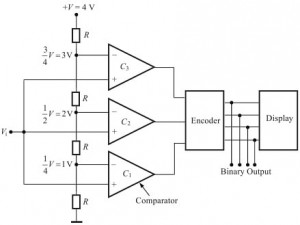
As shown above, three resistors of value R drives the comparators C1 , C2, C3. Let the input voltage Vi = 1v, +V= 4V and comparators i.e. C1 , C2, C3 voltages equal to 1V, 2V and 3V respectively. If the output of the C1 = +1 and C2=C3= 0, then we fed 001 as the input to the encoder which further converts it into 0001. This binary output drives the seven segment display to read 1V on it. With the help of this method, we read the voltages of magnitude 1V, 2V , 3V and we also add more comparators for more accurate readings as per our requirement.
(ii) Digital Ammeter (DAM):
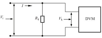
Digital ammeter uses a shunt resistor to produce a calibrated voltage proportional to the current flowing. As shown in the diagram, to read the current we must first convert the current to be measured into a voltage by using a known resistance RK. The voltage so developed is calibrated to read the input current.
(iii) Digital ohmmeter (DOM):
Digital ohmmeter is used to measure electrical resistance which obstructs the path to the flow of current.
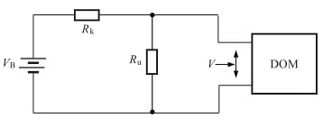
As shown in the diagram, resistance network comprising a known resistance RK and unknown resistance Ru used to develop voltage across the unknown resistance. The voltage is given by:
![]()
where VB = Voltage of the built-in battery
After calibrating voltage, meter can be calibrated in terms of ohms.
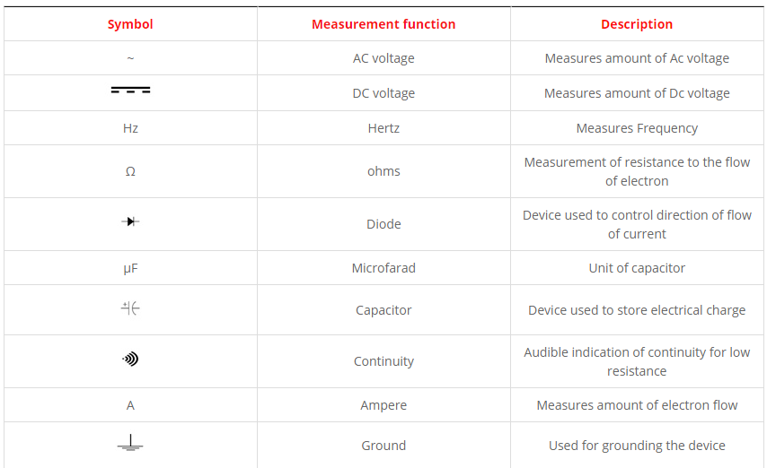
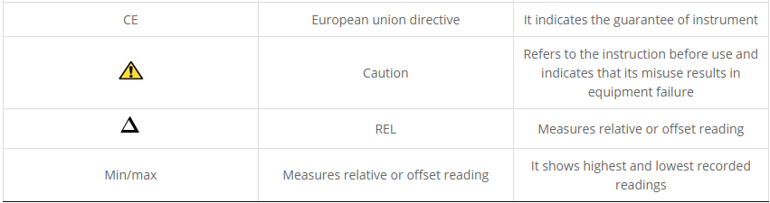
Multimeter symbols:
Some common Digital multimeter symbols and its description are given in the table below. These symbols are often found on the multimeter & its schematics are designed to symbolise components and reference values of electrical parameters.
Multimeter Safety Precaution:
- If the meter test leads are damaged then never use the meter.
- Always ensures that the test leads and dial are in right position for the desired measurement.
- When a test lead is plugged into the 10 A or 300mA input jack then never touch the probes to a voltage source.
- When power is applied never measure resistance in a circuit.
- While making measurements always keep your fingers behind the finger guards on the test probes.
- To avoid damage or injury, never use the meter on circuits that exceed 4800 watts.
- Replace the battery as soon as possible to avoid false readings which could lead to possible electric shock or personal injury.
- Be careful when working with voltages above 60 V DC or 30 V AC rms. Such voltages pose a shock hazard.
