JFET Common-Drain Amplifier:
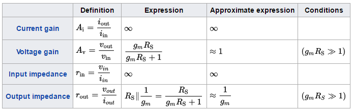
The common drain FET amplifier is similar to the common collector configuration of the bipolar transistor. A general common drain JFET amplifier, self-biased, is shown in figure below. This configuration, which is sometimes known as a source follower, is characterized by a voltage gain of less than unity, and features a large current gain as a result of having a very large input impedance and a small output impedance.
COMMON DRAIN AMPLIFIER CHARACTERISTICS:
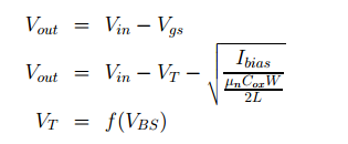
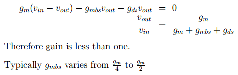
The output voltage of Common-Drain Amplifier is
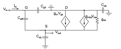
SMALL SIGNAL EQUIVALENT
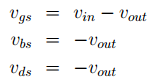
Writing KCL at the source node
INPUT AND OUTPUT RESISTANCE:
Input resistance of Common-Drain Amplifier,
![]()
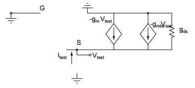
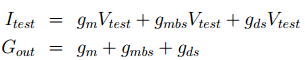
Output resistance of Common-Drain Amplifier,
To find the output resistance we apply a test voltage Vtest and find the current Itest through it.
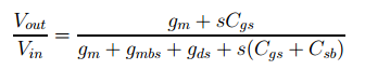
HIGH-FREQUENCY ANALYSIS:
The transfer function is obtained as
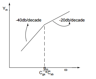
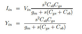
INPUT AND OUTPUT ADMITTANCE:
The input impedance is the measure of opposition to current flow (impedance) both static (resistance) and dynamic (reactance) from the electrical source into the load network being connected. The source network being the portion of the network that transmits power and the load network being the portion of the network that consumes power.
If the load network were replaced by a device with an impedance equal to the input impedance of the load network the characteristics of the source-load network would be the same from the perspective of the connection point. And so the voltage across and current through the input terminals would be identical to the original load network
The output impedance, source impedance, or internal impedance of an electronic device is the opposition exhibited by its output terminals to an alternating current (AC) of a particular frequency as a result of resistance, inductance and capacitance. It is the Thévenin equivalent impedance looking back into the output terminals.
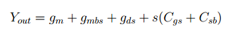
Output admittance,
Input admittance,
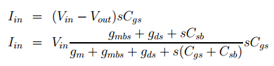
Approximating,
This shows it acts as a negative resistance and can be used in oscillators.
At low frequencies, the source follower pictured at right has the following small signal characteristics.