Measurement of Electrical Quantities with a CRO:
CRO is a very versatile instrument in laboratory for measurement of voltage, current, frequency and phase angle of any electrical quantity. But before we go ahead with discussion on measurement of electrical quantities with CRO, we should understand some basic oscilloscope patterns.
Basic Oscilloscope Patterns:
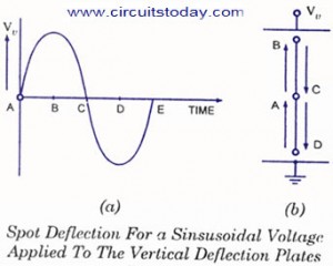
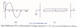
Assume that a sinusoidal voltage signal is applied to the horizontal deflection plates without applying any voltage signal to the vertical deflection plates, as shown in figure.
At point A in time, the voltage is zero so the spot remains undeflected at centre point of the screen. At point B in time, voltage Vh is maximum positive so the spot is at the extreme right end on the screen. At point C in time, once again the voltage is zero so the spot comes back to the central position on the screen. At point D in time, the voltage is maximum negative and so the spot is at the extreme left end on the screen. At point E in time, the voltage is zero so the spot returns to the central position of the screen. This way for next voltage cycle the spot again moves from point A to point B on the screen. So we get a horizontal line on the screen. One thing is to be kept in mind that this horizontal line is in the central position vertically as no voltage has been applied to vertical defection plates.
If sinusoidal voltage signal is applied to the vertical deflection plates without applying any voltage signal to horizontal deflection plates then we get a vertical line on the screen of CRO, as shown in figure. This line would be in the central position on the screen horizontally.
MEASUREMENT OF PHASE DIFFERENCE:
We have discussed that when two sinusoidal voltage signals of equal frequency having some phase difference are applied to the deflection plates of CRO, a straight line or an ellipse appears on the screen. In the case of straight line appearing on the screen, phase angle difference would be zero or 180° but in case of an ellipse we will have to use a formula for determination of phase difference.
Let there be two sinusoidal voltage signals given by
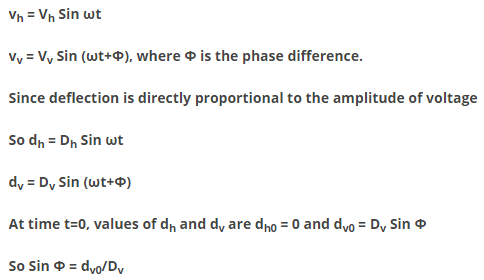
Graphical meaning of dv0 and Dv are shown in the figure. Thus the phase difference between two sinusoidal voltages of equal frequency can be determined by measuring dv0 and Dv.
MEASUREMENT OF FREQUENCY OF A VOLTAGE SIGNAL:
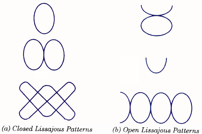
The patterns obtained on CRO screen and discussed in previous sections are called the Lissajous patterns. A Lissajous pattern is a pattern which is stationary on the screen of a CRO. It means that the spot traces out the same pattern for every cycle of a voltage signal. As we have already studied that the ratio of frequencies of vertical and horizontal voltage signals should be a rational or fractional number to have steady pattern. So the condition for having a Lissajous pattern on the CRO screen is
Lissajous patterns are usually of two types. First one is closed Lissajous pattern and has no free end. Second one is open Lissajous pattern and has free ends. Both types of Lissajous patterns are shown in figure.
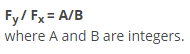
In a Lissajous pattern ratio of frequency of vertical signal to the frequency of horizontal signal is equal to the ratio of positive Y-peaks to positive X-peaks in that pattern.
![]()
Thus by counting the positive Y-peaks and X-peaks on a Lissajous pattern, ratio of frequencies of two voltage signals can be determined. In case of an open Lissajous pattern, free end is treated as half peak. This will be clear from examples.
Voltage signal of unknown frequency is applied to the vertical deflection plates and horizontal deflection plates are supplied by an accurately calibrated variable frequency source. Frequency of the variable frequency source is adjusted until a stationary pattern appears on the screen. Now by reading the value of frequency of horizontal signal, with the help of calibrated scale, frequency of voltage signal applied to vertical deflection plates can be known.
In case single loop stationary pattern is obtained the frequency of the sinusoidal voltage applied to vertical deflection pates is the same as that of the voltage applied to horizontal deflection plates. In case complex Lissajous figure is obtained, the frequency of alternating voltage may be determined using the relation
Points of tangency to a vertical line / Points of tangency to a horizontal line = ωx/ωy = fx/fy
In both of the figures, the ratio of Y-peaks to X-peaks is equal so in both cases, ratios of frequencies of vertical and horizontal signals are same. But appearance of Lissajous patterns is different owing to different phase difference of voltage signals applied to vertical arid horizontal deflection plates.
Current Measurement with CRO:
Electrical current cannot be measured directly by an oscilloscope. However, it could be measured indirectly within scope by attaching probes or resistors. Resistor measures the voltage across the points and then substituting the value of voltage and resistance in Ohm’s law and calculates the value of electrical current. Another easy way to measure current is to use a clamp-on current probe with an oscilloscope.
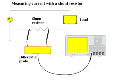
Method to Measure Current:
- Attach a probe with the register to an electrical circuit. Make sure that resistor’s power rating should be equal or greater than the power output of the system.
- Now take the value of resistance and plug into Ohm’s Law to calculate the current.
According to Ohm’s Law,