Overview: What is Retardation Plate?
A retardation plate is an optically transparent material which resolves a beam of polarized light into two orthogonal components; retards the phase of one component relative to the other; then recombines the components into a single beam with new polarization characteristics.
Birefringence:
To better understand phase retardation, birefringence must first be discussed. Most optical materials are isotropic, i.e. having the same optical properties (and therefore one index of refraction) regardless of the direction of propagation through the material. An anisotropic material possesses different optical, electric, piezoelectric and elastic properties dependent on the orientation of the material. Crystal such as quartz, calcite and sapphire are common anisotropic materials. Polarized light propagating through such crystals will experience a different index of refraction for different directions of propagation and polarization orientations. This phenomenon is known as birefringence.
Composition of Retardation Plate:
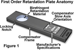
Retardation plates are composed of optically anisotropic quartz, mica, and gypsum minerals ground to a precise thickness and mounted between two optical windows having flat (plane) faces, which are designed to introduce a fixed amount of retardation between the orthogonal wavefronts passing through the crystal. More recently, several manufacturers have shifted to the application of a highly aligned and stretched linear organic polymer to produce anisotropic retardation plates.
Retardation Waveform:
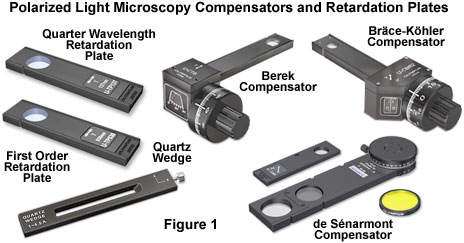
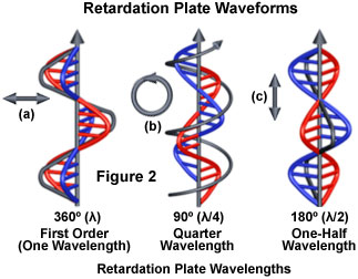
The three most common retardation plates produce optical path length differences of an entire wavelength (ranging between 530 and 570 nanometers), one-half wavelength (260-280 nanometers), or a quarter wavelength (137-150 nanometers). In addition, a variable optical path length can also be obtained by utilizing a tapering wedge-shaped design that covers a wide spectrum of wavelengths (up to six orders or about 3000 nanometers). The concept of a phase differential resulting from non-equivalent orthogonal wavefront propagation through retardation plates is illustrated in Figure 2. A wavefront passing through a full wave (one wavelength) retardation plate (Figure 2(a)) remains linearly polarized upon emerging and retains the same vibration plane. In contrast, the one-half wavelength plate (Figure 2(c)) rotates the plane of linearly polarized light by 90 degrees, while the quarter wavelength plate (Figure 2(b)) converts linearly polarized light into circularly polarized light (and vice versa). Retardation plates that introduce less than a quarter wavelength of phase shift produce elliptically polarized light.
The Quarter Wavelength Retardation Plate:
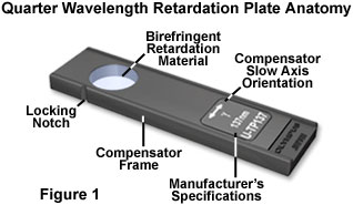
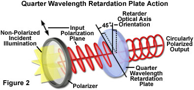
The quarter wavelength retardation plate is a common optical accessory for polarized light microscopy that operates by introducing a relative phase shift of 90 degrees between the orthogonal wavefronts (ordinary and extraordinary) passing through when the plate is illuminated with linearly polarized light. A phase shift of 90 degrees between the ordinary and extraordinary components converts the incident linear polarized light vibrations into either elliptical or circularly polarized light. Quarter wavelength retardation plates are useful for the qualitative analysis of conoscopic and orthoscopic images, and for the assessment of optical path differences in birefringent specimens.
Working process:
The quarter wavelength retardation plate is designed to introduce a relative retardation of exactly one-quarter wavelength (in the green or 550 nanometer region), or 90 degrees, between the ordinary and extraordinary wavefronts passing through the plate when the birefringent retardation material is illuminated by linearly polarized light at a 45-degree incident angle to the index ellipsoid, as illustrated in Figure 2. The resulting phase shift converts the linear input wavefront to a circularly polarized output wavefront. This action occurs because the orthogonal ordinary and extraordinary components have equal amplitudes when linear light oriented at a 45-degree angle to the principal (the fast or slow) axes is incident on a quarter wavelength retardation plate. In a similar manner, the quarter wavelength plate will convert an incoming circularly polarized wavefront into a linearly polarized wavefront.
Birefringence Observation in Quarter Wavelength Retardation:
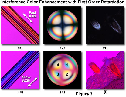
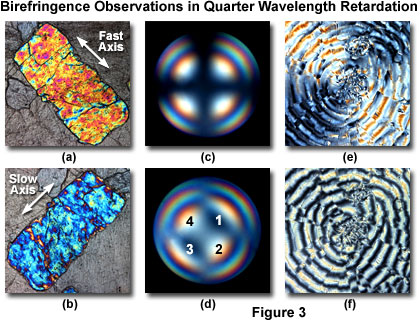
The primary use for quarter wavelength retardation plates is to determine the optical sign of birefringence from interference figures observed in conoscopic mode with a Bertrand lens (Figures 3(c) and 3(d)). Insertion of a quarter wavelength retardation plate resolves the center of a uniaxial interference figure (Figure 3(c)) into two dark spots (Figure 3(d)). If the dark spots are positioned at right angles to the slow vibration axis of the compensator crystal (in quadrants two and four; Figure 3(d)), then the sign of birefringence for the crystal is positive. Conversely, if the dark spots are positioned parallel to the compensator crystal slow axis (in quadrants one and three; Figure 3(d)), the crystal has a negative sign of birefringence.
The First Order (Full Wave) Retardation Plate:
Optical path differences ranging from a fraction of a wavelength up to several wavelengths can be readily estimated using a first order (or full wave) retardation plate. This versatile tool is known by several names, including a red plate, red-I (red-one) plate, lambda (λ) plate, gypsum plate, selenite plate, sensitive violet, or simply a color tint plate, and adds a fixed optical path difference between 530 and 560 nanometers to every wavefront in the field. The first order retardation plate is a standard accessory that is frequently utilized to determine the optical sign (positive or negative) of a birefringent specimen in polarized light microscopy.
Working process:
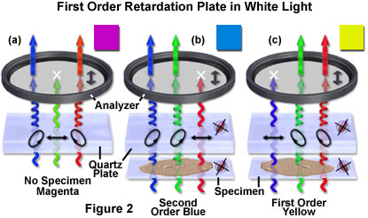
The first order retardation plate is designed to introduce a relative retardation of exactly one wavelength (in the green or 550 nanometer region) between the ordinary and extraordinary wavefronts passing through the plate when the birefringent retardation material is illuminated by linearly polarized light at a 45-degree incident angle to the index ellipsoid. As a result, green wavelengths emerge from the retardation plate crystal still linearly polarized and having the same orientation as when they entered the retardation material (parallel to the polarizer). These wavefronts are therefore able to pass a component vector through the analyzer. Subtracting the green wavelengths (blocked by the analyzer) from white light yields bright magenta-red, which results from a combination of all visible light spectral colors when the green wavelength band is missing. The magenta color observed in the microscope when a first order retardation plate is inserted into the optical train is a direct result of the events described above and is the origin for much of the common nomenclature describing this important qualitative tool.
Interference Color Enhancement with First Order Retardation:
This effect is illustrated with a pair of synthetic acetate fibers in Figures 3(a) and 3(b). Without a first order retardation plate in the optical path, the fibers appear birefringent with a 140-nanometer first order gray intensity superimposed on a jet black background (not illustrated). When the long axis of the synthetic acetate is oriented Northwest-Southeast and a first order retardation plate inserted into the microscope tube, the fibers acquire a first order yellow hue on a magenta background (Figure 3(a)). Rotating the microscope stage by 90 degrees (Northeast-Southwest) alters the interference color to second order blue (Figure 3(b)). From these results, the optical sign of birefringence for the acetate fibers is judged to be positive.