Non-Inverting Amplifier Circuit using an op-amp:
Operational amplifiers can be used in two basic configurations to create amplifier circuits. One is the inverting amplifier where the output is the inverse or 180° out of phase with the input, and the other is the non-inverting amplifier where the output is in the same sense or in phase with the input.
Non-Inverting Amplifier Circuit Basic:
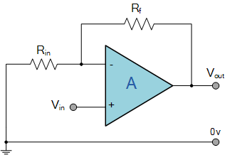
The basic non-inverting amplifier circuit using an op-amp is shown below. In this circuit the signal is applied to the non-inverting input of the amplifier. However the feedback is taken from the output via a resistor to the inverting input of the operational amplifier where another resistor is taken to ground. It is the value of these two resistors that govern the gain of the operational amplifier circuit.
The gain of the non-inverting amplifier circuit for the operational amplifier is easy to determine. The calculation hinges around the fact that the voltage at both inputs is the same. This arises from the fact that the gain of the amplifier is exceedingly high. If the output of the circuit remains within the supply rails of the amplifier, then the output voltage divided by the gain means that there is virtually no difference between the two inputs.
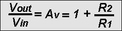
As the input to the op-amp draws no current this means that the current flowing in the resistors R1 and R2 is the same. The voltage at the inverting input is formed from a potential divider consisting of R1 and R2, and as the voltage at both inputs is the same, the voltage at the inverting input must be the same as that at the non-inverting input. This means that Vin = Vout x R1 / (R1 + R2). Hence the voltage gain of the circuit Av can be taken as:
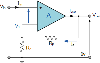
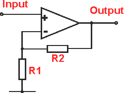
Non-inverting Operational Amplifier Configuration:
In the previous Inverting Amplifier tutorial, we said that for an ideal op-amp “No current flows into the input terminal” of the amplifier and that “V1 always equals V2”. This was because the junction of the input and feedback signal ( V1 ) are at the same potential.
In other words the junction is a “virtual earth” summing point. Because of this virtual earth node the resistors, Rƒ and R2 form a simple potential divider network across the non-inverting amplifier with the voltage gain of the circuit being determined by the ratios of R2 and Rƒ as shown below.
Equivalent Potential Divider Network:
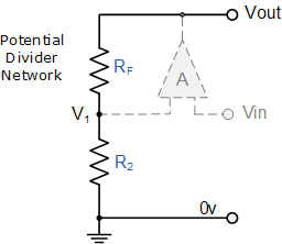
Then using the formula to calculate the output voltage of a potential divider network, we can calculate the closed-loop voltage gain ( A V ) of the Non-inverting Amplifier as follows:
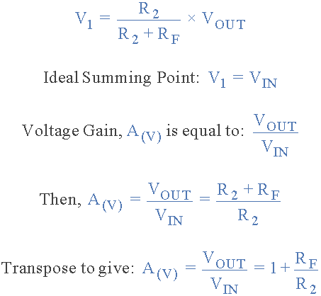
Then the closed loop voltage gain of a Non-inverting Operational Amplifier will be given as:
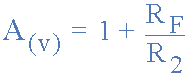
We can see from the equation above, that the overall closed-loop gain of a non-inverting amplifier will always be greater but never less than one (unity), it is positive in nature and is determined by the ratio of the values of Rƒ and R2.
If the value of the feedback resistor Rƒ is zero, the gain of the amplifier will be exactly equal to one (unity). If resistor R2 is zero the gain will approach infinity, but in practice it will be limited to the operational amplifiers open-loop differential gain, ( Ao ).
We can easily convert an inverting operational amplifier configuration into a non-inverting amplifier configuration by simply changing the input connections as shown.
Input- impedance of non-inverting amplifier:
It is often necessary to know the input impedance of a circuit. The input impedance of this non-inverting amplifier circuit is very high, and may typically be well in excess of 10^7 ohms. For most circuit applications this can be completely ignored. This is a significant difference to the inverting configuration of an operational amplifier circuit which provided only a relatively low impedance dependent upon the value of the input resistor.
AC coupling the non-inverting op-amp circuit:
In most cases, it is possible to DC couple the circuit. However. in this case it is necessary to ensure that the non-inverting has a DC path to earth for the very small input current that is needed. This can be achieved by inserting a high-value resistor, R3 in the diagram, to ground as shown below. The value of this may typically be 100 k ohms or more. If this resistor is not inserted the output of the operational amplifier will be driven into one of the voltage rails.
When inserting a resistor in this manner it should be remembered that the capacitor-resistor combination forms a high-pass filter with a cut-off frequency. The cut-off point occurs at a frequency where the capacitive reactance is equal to the resistance.
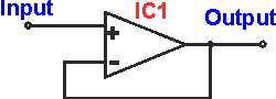
Op amp as a voltage follower:
A non-inverting amplifier using an op amp forms an ideal voltage follower. The very high gain of the op-amp enables it to present a very high impedance to the signal source whilst being able to accurately follow the voltage waveform.
An op amp is configured in its non-inverting amplifier format, linking the output directly to the inverting input and applying the input signal to the non-inverting input.
From the gain equation. it is possible to see that the voltage gain of this circuit is unity. Av = 1 + R2 / R1. R2 is zero and R1 is infinity, so the term R2/R1 is zero and this means that Av = 1.
Non-inverting amplifier using single supply:
Normally op amps are configured to use dual supplies – the chips are intended for use in this way. However, this is not always feasible if only one rail is present.
To enable the op amp to run with just one power rail, the positive and negative rails have to be simulated by operating the amplifier half way between the rail and ground, and ensuring the decoupling is sufficient in all the required areas. This is often referred to as a virtual ground technique.
To create the virtual ground, two resistors form a voltage divider so that the half the rail voltage, Vcc/2 appears at the non-inverting input of the op-amp.
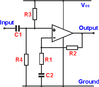
This circuit works well, but when using it a few design issues must be remembered:
- Resistors R3 & R4: These two resistors form the bias for the non-inverting amplifier, setting the input voltage and operating point. Typically they are set to provide half the supply voltage and therefore they will be equal in value. Values of around 100kΩ are typically chosen because they determine the input impedance. To incoming signals they are in parallel with each other and the input impedance of the op-amp itself is normally much higher and is often ignored – although check for the given op amp. Assuming this and each resistor being 100 kΩ, then the resistance in parallel is 50Ω
- Capacitor C2 value: The value of this capacitor must be chosen to give a low impedance at low frequencies. It is typically chosen to be equal in impedance to R1 at the lowest frequency required – this will give a -3dB fall at this frequency.
- Capacitor C2 type: It is important that this capacitor must be a low leakage type. If not the leakage could cause the output to hit the voltage rail if there is some gain in the circuit. Typically ceramic or tantalum types are best. Electrolytic types have a higher leakage and may not be suitable.
- Operating range: Dependent upon the requirements for the non-inverting amplifier, it may be necessary to choose an op amp that is able to operate with its output voltage close to either voltage rail. In this way, the maximum output voltage swing can be obtained.
This type of circuit is often very useful when only one supply line is available. Often it is more convenient to adopt this approach that provide an additional supply rail.
