Wave Optics : To explain some phenomena, such as interference and diffraction of light, it is necessary to go beyond geometrical optics.
Huygens’ Principle
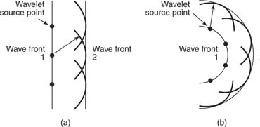
Huygens considered light to be a wave. He envisioned a wave crest advancing by imagining each point along the wave crest to be source point for small, circular, expanding wavelets, which expand with the speed of the wave. The surface tangent to these wavelets determines the contour of the advancing wave. Figure 1 illustrates Huygens’ construction for a plane wave (a) and for a spherical wave (b).
Huygens’ principle can be used to derive the law of reflection and the law of refraction. Note that the observed laws of geometric optics follow from the assumption that light is a wave.
Interference
Because light is a wave, the superposition principle is valid to determine the constructive and destructive interference for light waves. Interference in light waves is not easy to observe because the wavelengths are so short. For constructive interference, two waves must have the two contributing crests and the two troughs arriving at the same time. For destructive interference, a crest from one wave and a trough from the other must arrive at a given point at the same time.
Young’s experiment
Thomas Young first demonstrated interference from light waves with a double slit. The schematic diagram for this experiment is shown in Figure 2.
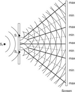
The single light source is located at S 0, and the light goes through two very narrow openings at S 1 and S 2. (A single light source is necessary because the light waves must have identical frequency and phase. The light beam is also considered to be of one color.) Each of the slits act as a source for circular expanding waves. The points of intersection of two crests, one from each slit, are points of constructive interference. The point of intersection of a crest from one slit and a trough from the other slit is a point of destructive interference. Therefore, the interference pattern called fringes, consisting of alternating light and dark bars, will be seen on the screen.
To better understand how these points are formed, Figure 3 illustrates the rays coming through two slits that are directed to the point P on the screen.
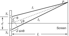
The difference in path length of the two rays is given by d sin θ = l 2 = l 1. If the path difference is a whole number of wavelengths, then constructive interference takes place. If the paths differ by a half number of wave lengths, destructive interference occurs. Using n to represent any integer, the two cases may be written
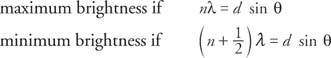
where λ is the wavelength and d is the distance between the two slits. Note : This figure is not to scale: The distance to the screen ( L) is much greater than the distance between the slits ( d).
