Shear Force and Bending Moment Diagrams:
Beam is one of the most important structural components.Beams are usually long, straight, prismatic members and always subjected forces perpendicular to the axis of the beam
- A Shear Force Diagram (SFD) indicates how a force applied perpendicular to the axis (i.e., parallel to cross-section) of a beam is transmitted along the length of that beam.
- A Bending Moment Diagram (BMD) will show how the applied loads to a beam create a moment variation along the length of the beam.
Types of Supports:
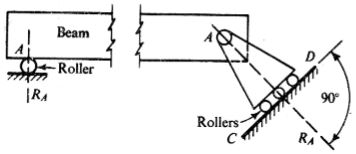
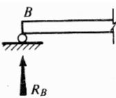
(a) Roller Support – resists vertical forces only
(b) Hinge support or pin connection – resists horizontal and vertical forces
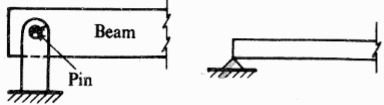
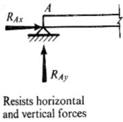
- Hinge and roller supports are called as simple supports
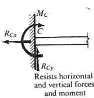
(c) Fixed support or built-in end:
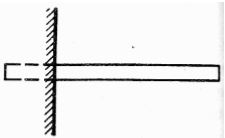
- The distance between two supports is known as “span”.
Shear Force:
Shear force has a tendency to slide the surface, it acts parallel to surface.
Only for distributed load not for point load.
Bending Moment:
Any moment produced by forces acting on the beam must be balance by an equal opposite moment produced by internal forces acting in beam at the section. This moment is called bending moment.
Only for distributed and concentrated load not for couple.
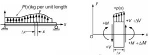
- The necessary internal forces to keep the segment of the beam in equilibrium are
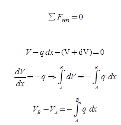
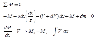
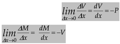
Differential equations of equilibrium:
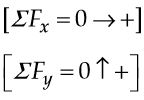
Sign Conventions :
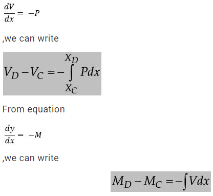
So the differential equations would be:
From equation:
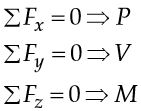
Statically Determinate Beam:
A beam is said to be statically determinate if all its reaction components can be calculated by applying three conditions of static equilibrium i.e.,
![]()
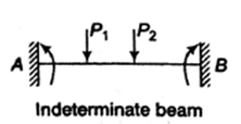
Statically Indeterminate Beam:
When the number of unknown reaction components exceeds the static conditions of equilibrium, the beam is said to be statically indeterminate.