Digital Multimeter:
Digital multimeter is a test equipment which offers several electronic measurement task in one tool. It is also known as the voltmeter or Ohm meter or Volt Ohm meter. The standard and basic measurements performed by multimeter are the measurements of amps, volts, and ohms. Apart from that, these digital multimeters perform many additional measurements by using digital and logic technology.
Working Principle of Digital Multimeter:

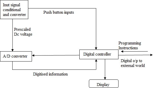
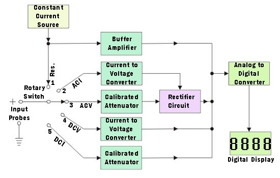
As shown in block diagram, in a typical Digital multimeter the input signal i.e ac or dc voltage, current, resistance, temperature or any other parameter is converted to dc voltage within the range of the ADC. The analog to digital converter then converts the pre-scaled dc voltage into its equivalent digital numbers which will be displayed on the display unit. Sometimes, digital controller block is implemented with a microcontroller or a microprocessor manages the flow of information within the instrument. This block will coordinate all the internal functions as well as transferring information to external devices such as printers or personal computer. In the case of some hand held multimeter some of or all of these blocks may be implemented in a VLSI circuit while A/D converter and display driver can be in the same IC.
Features of Digital Multimeter:
Now a day, wide range of digital multimeters are available in the market. But their features make it a good multimeter. Some of the features which are very useful and should be there in a multimeter are:
Auto-Rang: This feature enables multimeter to change their internal range according to the requirement to detect the correct voltage, current, or resistance of the circuit. It has an ability to stop the meter at the particular range and prevent the overloading if the meter is in volt range. Such multimeters are of high quality and have more features.
A Back-Lit LCD: It is a fancy feature, but felt very useful in dark situations when there is no other light source for watching reading in the multimeter.
Auto-Off: It is a great feature but normally comes in higher end version. It facilitates user to forget to turn the meter off when it is not in use.
Decent Probes: Decent probes are bonus above all. In multimeters normally leads are used which get damage at flex point. So it is better to use probes which make work easier and easy to replace if get damaged.
Auto Polarity: It is an important feature that shows the polarity of the current. When the voltage of current being measured shows positive reading (i.e. same polarity to meter connections) and if it shows negative (i.e. opposite polarity to meter connections). Such facility was not available in an analog multimeter and the meter deflects backwards and reverses back to take the reading accurately.

Tutorial for Current Measurement:
Current Measurement
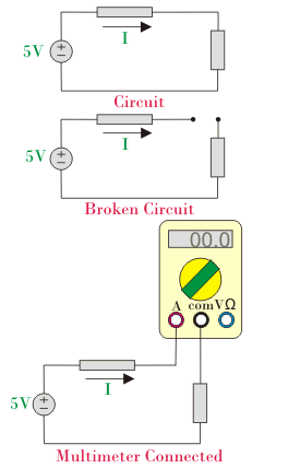
The measurements of voltage and resistance are most simple and can be done with certain precaution if required. But in the case of current measurement firm precaution is obligatory. Reading current is quite tricky because current should be measured in series. To do so, the flow of current is interrupted and keeps the digital multimeter in-line so that current passes through DMM. The rest of the connection is same as done in the case of voltage measurement and resistance

Digital multimeter has two ports; A and µA mA for measurement of current. The reason behind the two ports is to avoid overloading. In digital multimeter current has to pass through a fuse and if large current passes through the fuse it will blow out. A port is designated for large current and µA mA for small current. For measuring large current, plug one of the cords in A port and other in COM port. For measuring small current in a circuit, plug one cord in µA mA and the other in COM. While doing the connection, one more thing keeps in consideration and that is the direction of the current. A multimeter is connected in such a way that current enters from A port and leaves the DMM from the COM port, as shown in a figure. Most of the multimeter uses direct current. But if the circuit is drawing alternate current then you should use non-contact tester rather than the multimeter.
Multimeter Parts and functions:
Digital Multimeter is divided into three parts:
(i) Display: The LCD screen present on the upper portion of the multimeter basically displays four or more digits and also shows negative value if necessary. A few or today’s multimeters have illuminated the display for better viewing in low light situations.
(ii) Selection Dial: It allows the user to set the multimeter to read different electrical parameter such as milliamps (mA) of current, voltage, resistance, capacitance etc. You can easily turn the dial anywhere for specific parameter measurement.
(iii) Ports: Two ports are available on the front of every multimeter except in some four ports are available for measuring current in mA or A. We plugged two probes into these ports which are of different colour i.e. one is of red colour and other is of black colour.Ports are:
Multimeter leads:
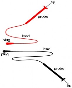
In the box of multimeter, we got leads of different colours. Here we are going to explain these leads in detail. Multimeter leads are subdivided into four parts:
(i) Red lead
- Connected to voltage, resistance or ampere port.
- Considered as a +ve connection of a circuit
(ii) Black lead
- Connected to the common or ground port
- Considered as a -ve connection of a circuit

(iii) Probes:
These are the handles used to hold the tip on the tested connection. There are different types of probes available on multimeter are:
(iv) Tip:
