What is Parallel Diode Configuration?
Diodes are frequently connected in parallel in switching power supplies in order to share the current. Thermal Runaway depends on the diode package and the heat-sink (dissipation) that they are mounted on. Provided enough dissipation in the design, higher current can be delivered when the “diodes are in parallel configuration”.
In a parallel connection, diode with the lowest forward biased voltage drop will try to conduct more current causing Thermal runaway. Diodes in parallel with the same polarity each behave no differently than a single diode. However, due to the fact that the current into each diode is lower because of the current divider rule, each diode will have less current flowing through it, and therefore its voltage drop will be lower, as this is a characteristic of diodes. Therefore, assuming the diodes are all very similar in Vf, the overall voltage drop of the parallel combination of diodes will be lower than it would be for a single diode. Although each individual diode’s current capability does not change, the parallel combination of diodes can handle more current overall, once again because of the current divider rule.
In parallel, the drop will stay the same (reverse leakage and capacitance will add), but the current capability may tend to decrease due to the possibility of thermal runaway. This can be avoided this somewhat by placing the diodes in thermal contact with each other, and/or using a small resistor in series with each.

Determine the voltage Vo for the network of the figure shown.
Initially, it would appear that the applied voltage will turn both diodes “on”. However, if both were “on” the 0.7-V drop across the silicon diode would not match the 0.3 V across the germanium diode as required by the fact that the voltage across parallel elements must be the same. The resulting action can be explained simply by realizing that when the supply is turned on it will increase from 0 to 12 V over a period of time—although probably measurable in milliseconds. At the instant during the rise that 0.3 V is established across the germanium diode it will turn “on” and maintain a level of 0.3 V. The silicon diode will never have the opportunity to capture its required 0.7 V and therefore remains in its open-circuit state as shown in Figure 1.

So,

The voltage Vo depends on the type of Si and Ge diodes.
Using the “standard” forward voltage drop of a Ge = 0.2 volts and a Si = 0.7 volts the Ge dominates and Vo = 11.8 volts.
What is thermal runaway?
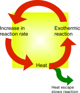
Thermal runaway describes a process that is accelerated by increased temperature, in turn releasing energy that further increases temperature. Thermal runaway occurs in situations where an increase in temperature changes the conditions in a way that causes a further increase in temperature, often leading to a destructive result.
Some electronic components develop lower resistances or lower triggering voltages as their internal temperature increases. If circuit conditions cause markedly increased current flow in these situations, increased power dissipation may raise the temperature. A positive feedback effect of thermal runaway can cause failure, sometimes in a spectacular fashion (e.g. electrical explosion or fire). To prevent these hazards, well-designed electronic systems typically incorporate current limiting protection, such as thermal fuses, circuit breakers, or current limiters.