OPERATIONAL AMPLIFIER MODES OF OPERATION:
The operational amplifier or OP-AMP is a direct coupled, high gain amplifier used to perform a wide variety of mathematical operation used to perform like summation, subtraction, multiplication, differentiation and integration etc. In analog computers it is often referred to as the basic linear (or analogue) integrated circuit (IC). The operational amplifier works in different modes depending on the nature of its job. These modes are explained below.
Single-ended Operation:
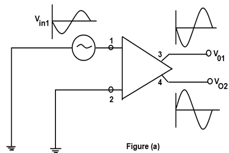
when a differential amplifier is operated in this mode, one input is ground and the signal voltage is applied only to the other input. In Figure (a) input signal is applied to terminal 1 and terminal 2 is ground.

Given Figure shows that an amplified and inverted output signal is obtained at V01 but an equally amplified and in phase signal appears at V02 which is terminal 4.
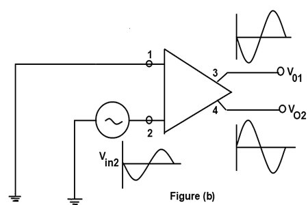
When input signal Vin2 is applied to input terminal 2, an amplified and inverted signal appears at output terminal 4 whereas equally amplified but in phase signal appears at terminal 3 this is shown in Figure (b).

Differential Operation:
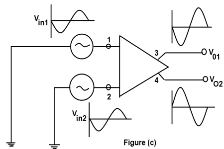
In this mode, two opposite polarity (out of phase) signals are applied to the inputs as shown in Figure (c).

This type of operation is also referred to as double ended operation. Input signal at each input terminal causes signal to appear at both output terminals. The resultant output signals have a peak value twice the value for single ended operation.
Common Mode Operation:
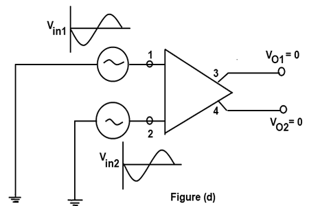
If two in phase and equal signals are applied at the two input terminals, the resultant output signal at each output terminal would be zero this is shown in Figure (d). in other words the output between collectors would be zero.

Inverting and non-inverting Inputs:
When positive Vin1 acts alone, it produce a differential output voltage with terminal 4 positive with respect to terminal 3 that is why the input terminal 1 is called noninverting input terminal. When positive Vin2 acts alone, the output voltage is inverted and terminal 3 becomes positive with respect to terminal 4. That is why input terminal 2 is called inverting terminal. It can be see in Figure (a) and (b).
