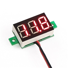
What is Digital Voltmeter:
Voltmeter is an electrical measuring instrument which is used to measure potential difference between two points. The voltage to be measured may be AC or DC. Two types of voltmeters are available for the purpose of voltage measurement i.e. analog and digital. Analog voltmeters generally contain a dial with a needle moving over it according to the measur and hence displaying the value of the same.With the passage of time analog voltmeters are replaced by digital voltmeters due to the same advantages associated with digital systems. Although analog voltmeters are not fully replaced by digital voltmeters, still there are many places where analog voltmeters are preferred over digital voltmeters. Digital voltmeters display the value of AC or DC voltage being measured directly as discrete numerical instead of a pointer deflection on a continuous scale as in analog instruments.
Working Principle of Digital Voltmeter:

The block diagram of a simple digital voltmeter is shown in the figure. Explanation of various blocks Input signal: It is basically the signal i.e. voltage to be measured. Pulse generator: Actually it is a voltage source. It uses digital, analog or both techniques to generate a rectangular pulse.
The width and frequency of the rectangular pulse is controlled by the digital circuitry inside the generator while amplitude and rise & fall time is controlled by analog circuitry. AND gate: It gives high output only when both the inputs are high. When a train pulse is fed to it along with rectangular pulse, it provides us an output having train pulses with duration as same as the rectangular pulse from the pulse generator.

NOT gate: It inverts the output of AND gate.
 Output of NOT gate
Decimal Display: It counts the numbers of impulses and hence the duration and display the value of voltage on LED or LCD display after calibrating it.

Now we are in a situation to understand the working of a digital voltmeter as follows:
- Unknown voltage signal is fed to the pulse generator which generates a pulse whose width is proportional to the input signal.
- Output of pulse generator is fed to one leg of the AND gate.
- The input signal to the other leg of the AND gate is a train of pulses.
- Output of AND gate is positive triggered train of duration same as the width of the pulse generated by the pulse generator.
- This positive triggered train is fed to the inverter which converts it into a negative triggered train.
-
- Output of the inverter is fed to a counter which counts the number of triggers in the duration which is proportional to the input signal i.e. voltage under measurement.
- Thus, counter can be calibrated to indicate voltage in volts directly.
We can see the working of digital voltmeter that it is nothing but an analog to digital converter which converts an analog signal into a train of pulses, the number of which is proportional to the input signal. So a digital voltmeter can be made by using any one of the A/D conversion methods.

On the basis of A/D conversion method used digital voltmeters can be classified as:
- Ramp type digital voltmeter
- Integrating type voltmeter
- Potentiometric type digital voltmeters
- Successive approximation type digital voltmeter
- Continuous balance type digital voltmeter
Advantages Associated with Digital Voltmeters:
- Read out of DVMs is easy as it eliminates observational errors in measurement committed by operators.
- Error on account of parallax and approximation is entirely eliminated.
- Reading can be taken very fast.
- Output can be fed to memory devices for storage and future computations.
- Versatile and accurate
- Compact and cheap
- Low power requirements
- Portability increased
