Diode equivalent models:
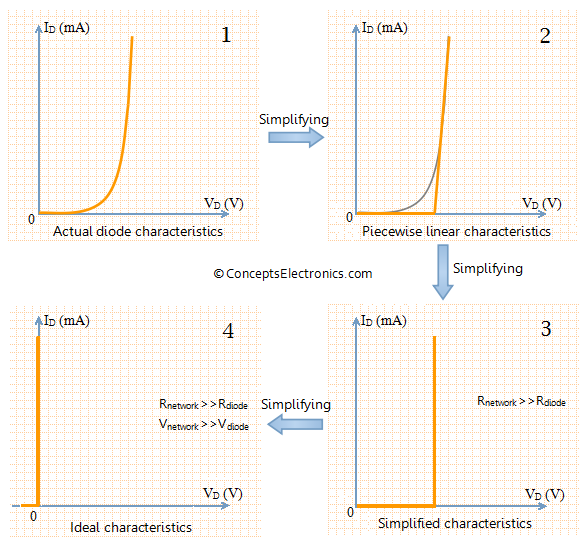
The diode can be modeled in three different ways depending on the accuracy required. Three models with decreasing accuracy are listed below
- Piece-wise linear model
- Simplified model
- Ideal diode model
Piece-wise linear model:
The piece-wise linear model, as the name suggests, is a model in which the characteristics of diode is approximated by “piece-wise linear” line segments. The graph given below shows piece-wise linear characteristics of diode along with the its model.
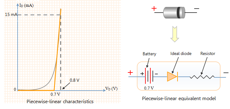
In the graph shown on left, the actual characteristics of diode is superimposed by piece-wise linear characteristics (shown in amber color). It is clear that the piece-wise linear characteristics do not exactly represent the characteristics of diode, especially near the knee of the curve.
- Consider the horizontal line from (0 to 0.7 V) in the piece-wise characteristic curve. The horizontal line indicates that the current flowing through diode is zero for voltages between 0 and 0.7 V. To model this behavior, we put a battery of 0.7 V in the equivalent diode model. This does not mean that diodes are a source of voltage. When you measure the voltage across an isolated diode, the instrument will show zero value. The battery simply indicates that it opposes the flow of current in forward direction until 0.7 V. As the voltage becomes larger than 0.7 V, the current starts flowing in forward direction.
- An ideal diode is also connected in series with the battery which indicates that no current flows in the circuit in reverse biased condition.
- Now consider the (almost) vertical line in the piece-wise linear characteristics. This straight line indicates constant slope. Slope in the V-I graph indicates resistance. So we add a resistor in the diode model. The value of resistance can be found from the graph. We can see from the graph that the diode current changes from 0 to 15 mA for a voltage change from 0.7 to 0.8 V. Thus the average value of resistance is (0.8 V-0.7 V)/(15 mA-0 mA) = 6.67 Ω. Thus the value of resistance in the equivalent model is approximately 6.67 Ω.
Simplified Diode model:
In the section on piece-wise linear model, we learnt that the average resistance of diode in forward bias configuration is very less. In the example discussed, the average resistance was merely 6.67 Ω. Such small value of resistance can usually be ignored in comparison with other elements in the circuit. Hence the characteristic and diode model will be as follows.
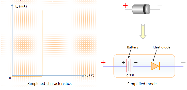
The equivalent model in this case consists of a battery and an ideal diode. The battery indicates that the current flowing through the diode in forward bias condition is zero until the diode voltage reaches 0.7 V (for Si).
Ideal diode model:
The piece-wise linear model represents the diode model in piece-wise linear manner. The simplified diode model ignores the effect of diode resistance in comparison with values of other elements of the circuit. Lets take the process of simplification one step further and establish that the voltage drop across the diode (0.7 V for Si) is negligible as compared to other voltage drops in the circuit. Hence the diode voltage drop can be ignored for simplification purpose. The resultant model is an ideal diode model. The figure shown below represents ideal diode along with its characteristics.
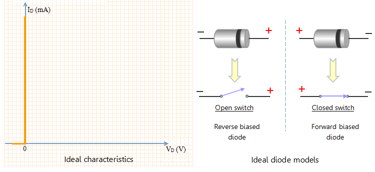
Take a look at the graph shown on the left-hand side. It indicates that the voltage drop across the diode is zero for any value of diode current (of course within the maximum limit). The ideal diode does not allow any current to flow in reverse biased condition. The current flowing through the diode is zero for any value of reverse biased voltage (within maximum limit).
Taking this into consideration, the ideal diode can be modeled as open or closed switch depending on the bias voltage.
- Ideal diode allows the flow of forward current for any value of forward bias voltage. Hence, Ideal diode can be modeled as closed switch under forward bias condition. This is shown in the figure above.
- Ideal diode allows zero current to flow under reverse biased condition. Hence it can be modeled as open switch. This is indicated in the above figure.
Summary: