What is Oscilloscope?
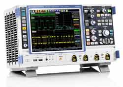
The oscilloscope or scope must be one of the most widely used and famous test instruments. The oscilloscope is a type of test equipment that allows signal voltages to display on a screen in a two-dimensional format. In this way, it is possible to see waveforms on the screen and understand how a circuit is performing. In view of this, the scope is able to provide a far great level of detail than simpler items of test equipment.
In view of its usefulness, the oscilloscope is an essential item in any electronics laboratory and many other environments. Often several scopes may be required in a lab with wide ranging specifications to accommodate the wide range of measurements and applications that they may need to fulfil.
Oscilloscope measurements:
The basic concept of the oscilloscope is that it displays waveforms in a two-dimensional format. The vertical axis is normally used to plot the incoming voltage, and the horizontal axis is normally used as a time axis. In this way the waveform voltage can be displayed as a function of time. In this way a sine wave would be displayed in its well known graphical format with a line undulating line with time on the horizontal axis. This is the most common way of using an oscilloscope
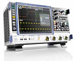
While it is useful to display a single waveform, many measurements and measurement techniques require more than on waveform to be displayed at any one time. This can be used to compare waveforms and look at how different waveforms interact or when events occur on more than one waveform. Many dual channel or multi-channel oscilloscopes exist that allow two or more waveforms to be displayed at the same time.
While the most usual way of displaying waveforms is to measure the instantaneous voltage on the vertical axis, and time on the horizontal axis, it is also possible to plot tow voltages against each other. In this way it is possible to display a Lissajous figure and look at the relative phases and voltages of two waveforms together.
At certain times it may be advantageous to be able to display three-dimensional images. The traditional way of achieving this was to modulate the intensity of the image by using a third waveform. There is often a “Z Axis” input at the rear of many oscilloscopes to achieve this.
Oscilloscope displays:
The display within an oscilloscope is obviously a very important element of the overall item of test equipment. Originally cathode ray tubes were used. These displays required very high voltages for their operation, and in addition to this, if bright steady waveforms were left displaying on the scope for extended periods of time, then this could damage the phosphor that illuminated and “worn” areas would appear with the waveform embedded on the display. Despite these and other problems, the cathode ray tube was used for very many years in the oscilloscope.
On some occasions it was necessary to store images for a short period of time. Before the days of digital technology, special storage oscilloscopes were used. These relied on a specialised storage cathode ray tube. This would operate by holding a charge on the screen in such a way that the area that was scanned remained illuminated. The “persistence” of the image could be altered so that the time the image remained on screen could be changed. This could be used for very slow waveforms that needs illuminated areas to have a long persistence to visualise the outline of the waveform.
With the advent of improved display technology and an increase in the level of digital forms of signal processing there has been a move to other forms of display including LCD and electroluminescent displays. Combined with the levels of processing available, both normal and storage functions are easily available. These displays are also less prone to damage and normally last the life of the oscilloscope.
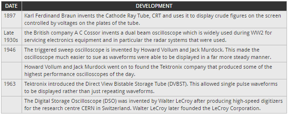
Oscilloscope history:
There have been several key dates and developments in the road to producing the oscilloscope of today. The oscilloscope history has relied on a number of key developments, each of which has enabled oscilloscope technology to progress a step further.
Types of Oscilloscope:
Since the first oscilloscopes were developed and produced a variety of different types of oscilloscope have been developed. These have appeared as the technology has developed and they have been focused on particular applications and measurements. As a result, when choosing an oscilloscope, one of the first decisions to be made is regarding the basic form of oscilloscope that is needed.
Some of the major forms of oscilloscope are summarised in the list below. These are described in much greater detail in a further page of this oscilloscope tutorial.
- Analogue oscilloscope
- Analogue storage oscilloscope
- Digital oscilloscope
- Digital storage oscilloscope
- Digital phosphor oscilloscope
- Digital sampling oscilloscope
Oscilloscopes have been in use within the electronics industry for many years. Even with many new developments occurring and a shift to greater levels of software within products there is no lessening of the importance of oscilloscopes. As technology develops, so the technology used within scopes has enabled them to provide higher levels of performance and to provide new and useful functions. With the continuing movement of technology, oscilloscope technology will also move forwards.
