Operational Amplifier as Differentiator:
Introduction:
An op-amp differentiator or a differentiating amplifier is a circuit configuration which produces output voltage amplitude that is proportional to the rate of change of the applied input voltage.
A differentiator with only RC network is called a passive differentiator, whereas a differentiator with active circuit components like transistors and operational amplifiers is called an active differentiator. Active differentiators have higher output voltage and much lower output resistance than simple RC differentiators.
Ideal Op-Amp Differentiator Circuit:
An op-amp differentiating amplifier uses a capacitor in series with the input voltage source, as shown in the figure below.
The input signal to the differentiator is applied to the capacitor. The capacitor blocks any DC content so there is no current flow to the amplifier summing point, X resulting in zero output voltage. The capacitor only allows AC type input voltage changes to pass through and whose frequency is dependent on the rate of change of the input signal.
At low frequencies, the reactance of the capacitor is “High” resulting in a low gain ( Rƒ/Xc ) and low output voltage from the op-amp. At higher frequencies, the reactance of the capacitor is much lower resulting in a higher gain and higher output voltage from the differentiator amplifier.
However, at high frequencies, an op-amp differentiator circuit becomes unstable and will start to oscillate. This is due mainly to the first-order effect, which determines the frequency response of the op-amp circuit causing a second-order response which, at high frequencies gives an output voltage far higher than what would be expected. To avoid this the high-frequency gain of the circuit needs to be reduced by adding an additional small value capacitor across the feedback resistor Rƒ.
Since the node voltage of the operational amplifier at its inverting input terminal is zero, the current, i flowing through the capacitor will be given as:
The charge on the capacitor equals Capacitance x Voltage across the capacitor
![]()
The rate of change of this charge is:
but dQ/dt is the capacitor current,i
from which we have an ideal voltage output for the op-amp differentiator is given as:
Therefore, the output voltage Vout is a constant -Rƒ.C times the derivative of the input voltage Vin with respect to time. The minus sign indicates a 180o phase shift because the input signal is connected to the inverting input terminal of the operational amplifier.
Op-amp Differentiator Waveforms:
If we apply a constantly changing signal such as a Square-wave, Triangular or Sine-wave type signal to the input of a differentiator amplifier circuit the resultant output signal will be changed and whose final shape is dependent upon the RC time constant of the Resistor/Capacitor combination.
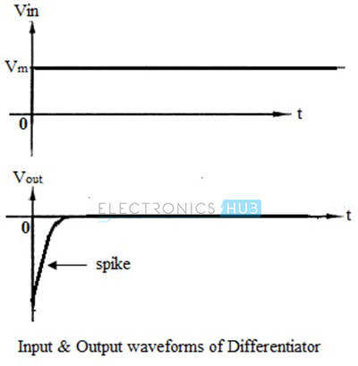
Input and Output Waveforms:
When a step input with amplitude Vm is applied to an op-amp differentiator, the output can be mathematically expressed as,
![]()
For simplicity, assume the product (C1.Rf) is unity.
Therefore, Vout = 0 because the amplitude V is constant.
But practically, the output is not zero since the input step wave takes a finite amount of time to rise from 0 volts to Vm volts. Hence the output appears like a spike at time t = 0, as shown in the figure below.
If the input to the differentiator is changed to a square wave, the output will be a waveform consisting of positive and negative spikes, corresponding to the charging and discharging of the capacitor, as shown in the figure below.
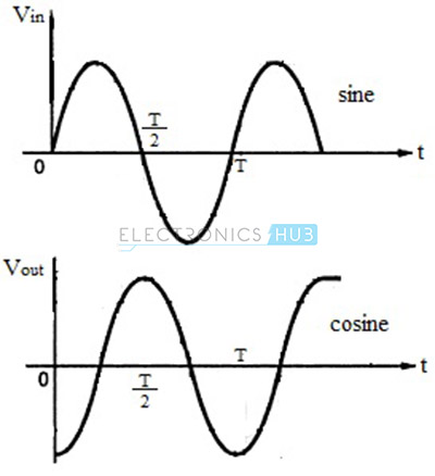
For sine wave input, which is mathematically represented as V (t) = Vm sin ωt, where Vm is the amplitude of the input signal and t is the period, the output of the differentiator is given as,
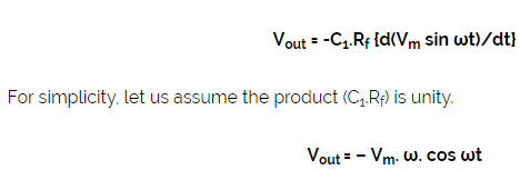
Thus the output of a differentiator for a sine wave input is a cosine wave and the input-output waveforms are shown in the figure below
Frequency Response of Ideal Differentiator:
The gain of an op-amp differentiator is directly dependent on the frequency of the input signal. Hence, for DC inputs where f = 0, the output is also zero. As the frequency of the input signal increases, the output also increases. The frequency response of an ideal differentiator is as shown in the figure below.
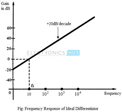
The frequency f1 is the frequency for which the gain of the differentiator becomes unity. It can be seen from the figure that for frequency less than f1, the gain is less than unity. For f1, the gain becomes the unity (0 dB) and beyond f1, the gain increases at 20dB per decade.
Practical Op-amp Differentiator Circuit:
For an ideal differentiator, the gain increases as frequency increases. Thus, at some higher frequencies, the differentiator may become unstable and cause oscillations which results in noise.
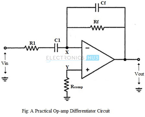
These problems can be avoided or corrected in a practical differentiator circuit which uses a resistor R1 in series with the input capacitor and a capacitor Cf in parallel with the feedback resistor, as shown in the figure below.
Frequency Response of Practical Differentiator:
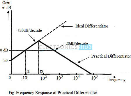
The gain of the practical differentiator increases with increasing frequency and at a particular frequency, f1, the gain becomes the unity (0 dB). The gain continues to increase at a rate of 20dB per decade till the input frequency reaches a frequency, f2.
Beyond this frequency of the input signal, the gain of the differentiator starts to decrease at a rate of 20dB per decade. This effect is due to the addition of the resistor R1 and capacitor Cf. The frequency response curve of a practical differentiator is as shown in the figure below.
Applications of Op-amp Differentiator:
- Differentiating amplifiers are most commonly designed to operate on triangular and rectangular signals.
- Differentiators also find application as wave shaping circuits, to detect high-frequency components in the input signal.
