RAMP Type Digital Voltmeter:
• The operating principle of a ramp type digital voltmeter is to measure the time that a linear ramp voltage takes to change from level of input voltage to zero voltage (or vice versa).
• This time interval is measured with an electronic time interval counter and the count is displayed as a number of digits on electronic indicating tubes of the output readout of the voltmeter.
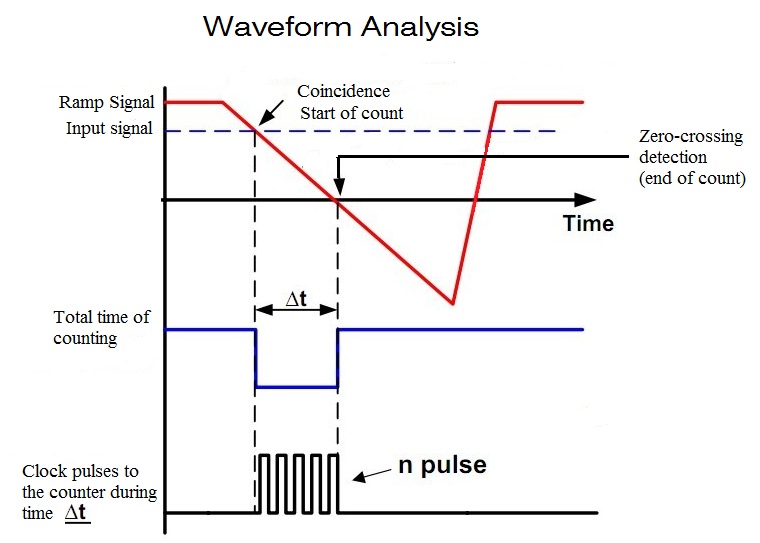
• The conversion of a voltage value of a time interval is shown in the timing diagram given below.
Working Process of RAMP Type DVM:
• At the start of measurement a ramp voltage is initiated.
• A negative going ramp is shown in Fig. but a positive going ramp may also be used.
• The ramp voltage value is continuously compared with the voltage being measured (unknown voltage).
• At the instant the value of ramp voltage is equal to that of unknown voltage.
• The ramp voltage continues to decrease till it reaches ground level (zero voltage).
• At this instant another comparator called ground comparator generates. a pulse and closes the gate.
• The time elapsed between opening and closing of the gate is t as indicated in Fig.
• During this time interval pulses from a clock pulse generator pass through the gate and are counted and displayed.
• The decimal number as indicated by the readout is a measure of the value of input voltage.
• The sample rate multivibrator determines the rate at which the measurement cycles are initiated.
• The sample rate circuit provides an initiating pulse for the ramp generator to start its next ramp voltage.
• At the same time it sends a pulse to the counters which set all of them to 0.
• This momentarily removes the digital display of the readout.
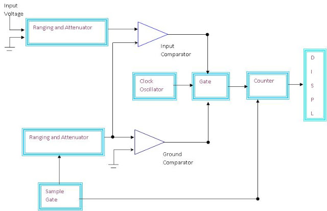
AT INPUT COMPARATOR:
An unknown voltage Vm is given to the input of non-inverting terminal. When the input at inverting terminal of op-amp is less than Vm out at the input comparator is positive otherwise it is negative. When Vr decreases below Vm it produces a positive going pulse,
this pulse makes the gating circuit to start and the pulse produced by the clock generator passes through the gating circuit. These pulses are counted by decade counter
AT GROUND COMPARATOR:
Ground comparator or zero level detector .so when the VR crosses zero and moves to negative values, the input at inverting terminal is greater than non-inverting terminal. So output of this comparator produces a negative going pulse which makes the gating circuit to
stop. Therefore the reading displayed on the display is the unknown voltage.
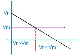
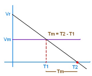
VOLTAGE TO TIME CONVERSION:
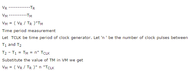
FEATURES OF RAMP TYPE DVM:
1)CONVERSION TIME:
![]()
Where n is proportional to Vm because the number of pulses depends upon Vm.
2) NOISE REJECTION:
If either AC signal or noise is superimposed on unknown DC voltage then error is introduced in voltage measurement. So noise effect is more. Therefore noise rejection is poor. Since stability of DVM depends on noise condition. Its stability is poor.
3) ACCURACY:
Value Internal components of ramp generator changes due to ageing then linearity of ramp changes then Vm also changes as shown in the figure and accuracy of measurement is affected.
