Summing amplifier using op-amp:
Summing amplifier is a type operational amplifier circuit which can be used to sum signals. The sum of the input signal is amplified by a certain factor and made available at the output .Any number of input signal can be summed using an opamp. The circuit shown below is a three input summing amplifier in the inverting mode.
Summing Amplifier Circuit:
In this simple summing amplifier circuit, the output voltage, ( Vout ) now becomes proportional to the sum of the input voltages, V1, V2, V3, etc. Then we can modify the original equation for the inverting amplifier to take account of these new inputs thus:
However, if all the input impedances, ( Rin ) are equal in value, we can simplify the above equation to give an output voltage of:
Summing Amplifier Equation:

We now have an operational amplifier circuit that will amplify each individual input voltage and produce an output voltage signal that is proportional to the algebraic “SUM” of the three individual input voltages V1, V2 and V3. We can also add more inputs if required as each individual input “see’s” their respective resistance, Rin as the only input impedance.
This is because the input signals are effectively isolated from each other by the “virtual earth” node at the inverting input of the op-amp. A direct voltage addition can also be obtained when all the resistances are of equal value and Rƒ is equal to Rin.
Note that when the summing point is connected to the inverting input of the op-amp the circuit will produce the negative sum of any number of input voltages. Likewise, when the summing point is connected to the non-inverting input of the op-amp, it will produce the positive sum of the input voltages.
A Scaling Summing Amplifier can be made if the individual input resistors are “NOT” equal. Then the equation would have to be modified to:

To make the math’s a little easier, we can rearrange the above formula to make the feedback resistor RF the subject of the equation giving the output voltage as

This allows the output voltage to be easily calculated if more input resistors are connected to the amplifiers inverting input terminal. The input impedance of each individual channel is the value of their respective input resistors, ie, R1, R2, R3 … etc.
Sometimes we need a summing circuit to just add together two or more voltage signals without any amplification. By putting all of the resistances of the circuit above to the same value R, the op-amp will have a voltage gain of unity and an output voltage equal to the direct sum of all the input voltages as shown:
The Summing Amplifier is a very flexible circuit indeed, enabling us to effectively “Add” or “Sum” (hence its name) together several individual input signals. If the inputs resistors, R1, R2, R3 etc, are all equal a “unity gain inverting adder” will be made. However, if the input resistors are of different values a “scaling summing amplifier” is produced which will output a weighted sum of the input signals.
Summing Amplifier Applications:
Summing Amplifier as Averaging Amplifier:
By using the proper input and feedback resistor values, a summing amplifier can be designed to provide an output voltage that is equal to the average of input voltages.
A summing amplifier will act as an averaging amplifier when both of the following conditions are met:
- All input resistors (R1, R2 and so on ) are equal in value.
- The ratio of any input resistor to the feedback resistor is equal to the number of input circuits.
Fig. below shows the circuit of averaging amplifier.
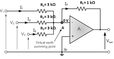
Here all input resistors are equal in value (3 KΩ). If we take the ratio of any input resistor to the feedback resistor, we get 3 kΩ/1 kΩ =3. This is equal to the number of inputs to the circuit.
the output voltage is given by:
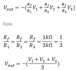
Note that Vout is equal to the average of the three inputs. The negative sign shows the phase reversal.
Summing Amplifier As Subtractor:
A summing amplifier can be used to provide an output voltage that is equal to the difference of two oltages.
Such a circuit is called a Subtractor and is shown in fig. below.
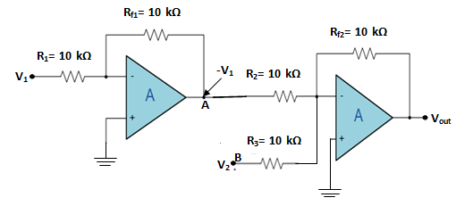
As we can see, this circuit will provide an output voltage that is equal to the difference between V1 and V2. The voltage V1 is applied to a standard inverting amplifier that has unity gain. Because of this, the output from the inverting amplifier will be equal to –V1. This output is then applied to the summing amplifier, also having unity gain along with V2.
Thus output from second OP-Amp is given by:
![]()
The gain of the second stage in the Subtractor can be varied to provide an output that is proportional to the difference between the input voltages.
Summing Amplifier Audio Mixer:
Another useful application of a Summing Amplifier is as a weighted sum digital-to-analogue converter. If the input resistors, Rin of the summing amplifier double in value for each input, for example, 1kΩ, 2kΩ, 4kΩ, 8kΩ, 16kΩ, etc, then a digital logical voltage, either a logic level “0” or a logic level “1” on these inputs will produce an output which is the weighted sum of the digital inputs.
Digital to Analogue Converter:
In this DAC summing amplifier circuit, the number of individual bits that make up the input data word, and in this example 4-bits, will ultimately determine the output step voltage as a percentage of the full-scale analogue output voltage.
Also, the accuracy of this full-scale analogue output depends on voltage levels of the input bits being consistently 0V for “0” and consistently 5V for “1” as well as the accuracy of the resistance values used for the input resistors, Rin.
