What is Rectifier?
A rectifier is an electrical device that converts alternating current (AC) to direct current (DC), a process known as rectification. Rectifiers have many uses including as components of power supplies and as amplitude modulation detectors (envelope detectors) of radio signals. Rectifiers are most commonly made using solid state diodes but other type of components can be used when very high voltages or currents are involved.
Half-wave rectification:
In half wave rectification, either the positive or negative half of the AC wave is passed, while the other half is blocked. Because only one half of the input waveform reaches the output, it is only 50% efficient if used for power transfer. Half-wave rectification can be achieved with a single diode in a single phase supply as shown in figure 6.1, or with three diodes in a three-phase supply.
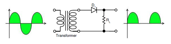
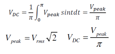
The output DC voltage of a half wave rectifier, given a sinusoidal input, can be calculated with the following ideal equations:
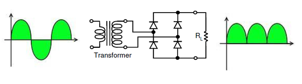
Full-wave rectification:
A full-wave rectifier converts both the positive and negative halves of the input waveform to a single polarity (positive or negative) at its output. By using both halves of the AC waveform full-wave rectification is more efficient than half wave.
When a simple transformer with out a center tapped secondary is used, four diodes are required instead of the one needed for half-wave rectification. Four diodes arranged this way are called a diode bridge or bridge rectifier as shown in figure 6.2. The bridge rectifier can also be used for translating a DC input of unknown or arbitrary polarity into an output of known polarity. This is generally required in electronic telephones or other telephony devices where the DC polarity on the two phone wires is unknown. There are also applications for protecting against accidental battery reversal in battery-powered circuits.
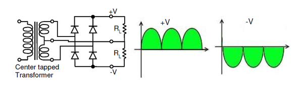
For single-phase AC, if the transformer is center-tapped, then two diodes back-to-back (i.e. anode-to-anode or cathode-to-cathode) can form a full-wave rectifier. Twice as many windings are required on the transformer secondary to obtain the same output voltage compared to the bridge rectifier above. This is not as efficient from the transformer perspective because current flows in only one half of the secondary during each positive and negative half cycle of the AC input.
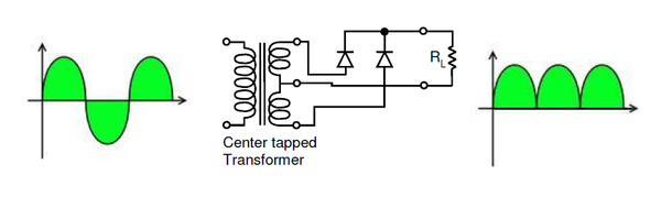
If a second pair of diodes is included as in figure 6.4 then both positive and negative polarity voltages with respect to the transformer center tap can be generated. One can also view this arrangement to be the same as adding a center tap to the secondary winding in the full-wave bridge rectifier from figure 4.

I have noticed you don’t monetize your site, don’t waste your traffic, you
can earn additional cash every month because you’ve got hi
quality content. If you want to know how to make extra money, search for: Mertiso’s tips best adsense alternative