What is Operational Amplifier?
An operational amplifier or OP-AMP is a DC-coupled voltage amplifier with a very high voltage gain. An Op-amp is basically a multistage amplifier in which a number of amplifier stages are interconnected to each other in a very complicated manner. Its internal circuit consists of many transistors, FETs and resistors.
Operational Amplifier Basics:
An Operational Amplifier, or op-amp for short, is fundamentally a voltage amplifying device designed to be used with external feedback components such as resistors and capacitors between its output and input terminals. These feedback components determine the resulting function or “operation” of the amplifier and by virtue of the different feedback configurations whether resistive, capacitive or both, the amplifier can perform a variety of different operations, giving rise to its name of “Operational Amplifier”.
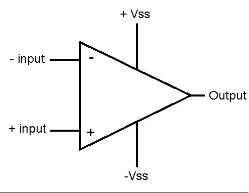
An Operational Amplifier is basically a three-terminal device which consists of two high impedance inputs, one called the Inverting Input, marked with a negative or “minus” sign, ( – ) and the other one called the Non-inverting Input, marked with a positive or “plus” sign ( + ).
The third terminal represents the operational amplifiers output port which can both sink and source either a voltage or a current. In a linear operational amplifier, the output signal is the amplification factor, known as the amplifiers gain ( A ) multiplied by the value of the input signal and depending on the nature of these input and output signals, there can be four different classifications of operational amplifier gain.
- Voltage – Voltage “in” and Voltage “out”
- Current – Current “in” and Current “out”
- Transconductance – Voltage “in” and Current “out”
- Transresistance – Current “in” and Voltage “out”
Since most of the circuits dealing with operational amplifiers are voltage amplifiers, we will limit the tutorials in this section to voltage amplifiers only, (Vin and Vout).
Differential Amplifier:
The circuit below shows a generalized form of a differential amplifier with two inputs marked V1 and V2. The two identical transistors TR1 and TR2 are both biased at the same operating point with their emitters connected together and returned to the common rail, -Vee by way of resistor Re.
The circuit operates from a dual supply +Vcc and -Vee which ensures a constant supply. The voltage that appears at the output, Vout of the amplifier is the difference between the two input signals as the two base inputs are in anti-phase with each other.
So as the forward bias of transistor, TR1 is increased, the forward bias of transistor TR2 is reduced and vice versa. Then if the two transistors are perfectly matched, the current flowing through the common emitter resistor, Re will remain constant.
Equivalent Circuit of an Ideal Operational Amplifier:
Op-amp Parameter and Idealized Characteristic:
-
Open Loop Gain, (Avo)
- Infinite – The main function of an operational amplifier is to amplify the input signal and the more open loop gain it has the better. Open-loop gain is the gain of the op-amp without positive or negative feedback and for such an amplifier the gain will be infinite but typical real values range from about 20,000 to 200,000.
-
Input impedance, (Zin)
- Infinite – Input impedance is the ratio of input voltage to input current and is assumed to be infinite to prevent any current flowing from the source supply into the amplifiers input circuitry ( Iin = 0 ). Real op-amps have input leakage currents from a few pico-amps to a few milli-amps.
-
Output impedance, (Zout)
- Zero – The output impedance of the ideal operational amplifier is assumed to be zero acting as a perfect internal voltage source with no internal resistance so that it can supply as much current as necessary to the load. This internal resistance is effectively in series with the load thereby reducing the output voltage available to the load. Real op-amps have output impedances in the 100-20kΩ range.
-
Bandwidth, (BW)
- Infinite – An ideal operational amplifier has an infinite frequency response and can amplify any frequency signal from DC to the highest AC frequencies so it is therefore assumed to have an infinite bandwidth. With real op-amps, the bandwidth is limited by the Gain-Bandwidth product (GB), which is equal to the frequency where the amplifiers gain becomes unity.
-
Offset Voltage, (Vio)
- Zero – The amplifiers output will be zero when the voltage difference between the inverting and the non-inverting inputs is zero, the same or when both inputs are grounded. Real op-amps have some amount of output offset voltage.
Open-loop Frequency Response Curve:
From this frequency response curve we can see that the product of the gain against frequency is constant at any point along the curve. Also that the unity gain (0dB) frequency also determines the gain of the amplifier at any point along the curve. This constant is generally known as the Gain Bandwidth Product or GBP. Therefore:
An Operational Amplifiers Bandwidth:
The operational amplifiers bandwidth is the frequency range over which the voltage gain of the amplifier is above 70.7% or -3dB (where 0dB is the maximum) of its maximum output value as shown below.