Bipolar Junction Transistor (BJT):
A Bipolar Junction Transistor (BJT) has three terminals connected to three doped semiconductor regions. In an N-P-N transistor, a thin and lightly doped P-type base is sandwiched between a heavily doped N-type emitter and another N-type collector; while in a P-N-P transistor, a thin and lightly doped N-type base is sandwiched between a heavily doped P-type emitter and another P-type collector. In the following, we will only consider NPN BJTs.
Working Principle of BJT:
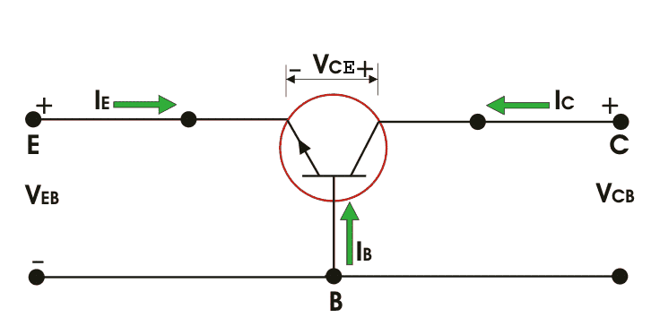
Figure 2, shows n-p-n transistor biased in the active region (See transistor biasing), the BE junction is forward biased whereas the CB junction is reversed biased. The width of the depletion region of the BE junction is small as compared to that of the CB junction.
The forward bias at the BE junction reduces the barrier potential and causes the electrons to flow from the emitter to base. As the base is thin and lightly doped it consists of very few holes so some of the electrons from the emitter (about 2%) recombine with the holes present in the base region and flow out of the base terminal.
This constitutes the base current, it flows due to recombination of electrons and holes (Note that the direction of conventional current flow is opposite to that of flow of electrons). The remaining large number of electrons will cross the reverse biased collector junction to constitute the collector current. Thus by KCL,
![]()
The base current is very small as compared to emitter and collector current.
![]()
Here, the majority charge carriers are electrons. The operation of p-n-p transistor is same as of the n-p-n, the only difference is that the majority charge carriers are holes instead of electrons. Only a small part current flows due to majority carriers and most of the current flows due to minority charge carriers in a BJT. Hence, they are called as minority carrier devices
Equivalent Circuit of BJT:
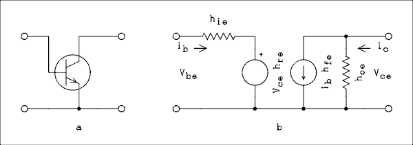
A p-n junction is represented by a diode. As a transistor has two p-n junctions, it is equivalent to two diodes connected back to back. This is called as the two diode analogy of the BJT.

i really needed a detailed explanation about this topic as we have seminar coming up in a day or two and so i was looking for a lot of resources and i was waiting for it to display , but to be honest it was really dissapoint to see a little content.
i completely agree with the content of the quality to be top notch , but sometimes especially in electronics QUANTITY matters too