PLANER MACHINE
Introduction:
The planer is a machine tool designed to produce plane and flat surface on a workpiece which is too large or too heavy. The workpiece is securely fixed on a table called platen, and it reciprocates horizontally against a single edged cutting tool. The surface machined may be horizontal, vertical or at an angle.
Operations of planer machine:
The planer is used for:
- Planing flat horizontal, vertical and curved
- Planing at an angle and machining
- Slots Planing
The planer are available in different types for doing different types and sizes of job; the most common being the standard and double housing planer.
Construction:
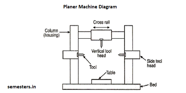
The main parts of the double Housing Planer machine are:
Bed and table:
The bed is a long heavy base and table made of cast iron. Its top surface is flat and machined accurately. The flat top surface has slots in which the workpiece can be securely clamped. The workpiece needs rigid fixing so that it does not shift out of its position. The standard clamping devices used on planer machine are: Heavy duty vice, T-holders and clamps, step blocks and stop. The table movement may be actuated by a variable speed drive through a rack and pinion arrangement, or a hydraulic system.
Housings:
The housings are the rigid and upright column like castings. These are located near the centre on each side of the base.
Cross rail:
The cross rail is a horizontal member supported on the machined ways of the upright columns. Guide ways are provided on vertical face of each column and that enables up and vertical movement of the cross rail. The vertical movement of the cross rail allows to accommodate workpiece of different heights. Since the cross rail is supported at both the ends, this type of planer machine is rigid in construction.
Tool heads:
Generally two tool heads are mounted in the horizontal cross rail and one on each of the vertical housing. Tool heads may be swiveled so that angular cuts can be made.
Driving and feed mechanism:
The tool heads may be fed either by hand or by power in crosswise or vertical direction. The motor drive is usually at one side of the planer near the centre and drive mechanism is located under the table.
The size of the planer is specified by the maximum length of the stroke, and also by the size of the largest rectangular solid that can be machined on it.
