What is Differential Amplifier?
A differential amplifier is the combination of inverting and non-inverting amplifier. A differential amplifier is a type of electronic amplifier that amplifies the difference between two input voltages but suppresses any voltage common to the two inputs. It is an analog circuit with two inputs 


where, 
A standard operational amplifier has two inputs, inverting and noninverting, we can also connect signals to both of these inputs at the same time producing another common type of operational amplifier circuit called a Differential Amplifier.
Basically, as we saw in the first tutorial about operational amplifiers, all op-amps are “Differential Amplifiers” due to their input configuration. But by connecting one voltage signal onto one input terminal and another voltage signal onto the other input terminal the resultant output voltage will be proportional to the “Difference” between the two input voltage signals of V1 and V2.
Differential Amplifier using Op-amp:
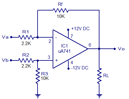
The circuit diagram of a differential amplifier using one opamp is shown below. R1 and R2 are the input resistors, Rf is the feedback resistor and RL is the load resistor.
Derivation for voltage gain.
Equation for the voltage gain of the differential amplifier using one opamp can be derived as follows. The circuit is just a combination of an inverting and non inverting amplifier. Finding the output voltages s of these two configurations separately and then summing them will result in the overall output voltage.
If Vb is made zero, the circuit becomes an inverting amplifier. The output voltage Voa due to Va alone can be expressed using the following equation.
![]()
When Va is made zero the circuit becomes a non inverting amplifier. Let V1 be the voltage at the non inverting input pin. Relation between Vb and V1 can be expressed using the following equation.
![]()
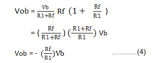
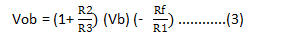
Output voltage Vob due to Vb alone is according to the equation
![]()
Let R1 = R2 and R3 =Rf then
Then overall output voltage is
Therefore overall gain is
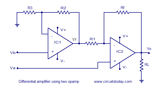
Differential amplifier using two opamps.
Circuit diagram of a differential amplifier using two opamps is shown below. Main advantage of differential amplifier with two opamps is that it has increased overall gain. R1 is the input resistor for IC1 and R3 is the input resistor for IC2. Rf is the feedback resistor. Va and Vb are the two input voltages and they are applied to the non inverting inputs of IC2 and IC1 respectively. RL is the load resistor. V+ and V- are the positive and negative supply voltages.
Derivation of voltage gain.
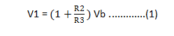
The equation for the output voltage V1 of the first opamp (IC1) is as follows.
V1 and Va are the inputs for the second stage (IC2). Output voltage due to Va alone is.

Output voltage due to Vb alone is
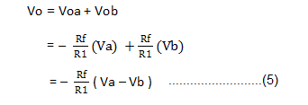
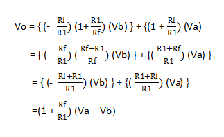
Overall output voltage Vo = Voa + Vob
![]()
Let R1 = R2 and Rf =R1, then we have
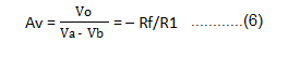
Therefore overall voltage gain Av can be expressed using the equation
![]()
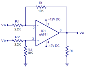
Practical differential amplifier.
A practical differential amplifier using uA741 opamp is shown below. With used components the amplifier has a gain of around 5. Remember the equation Av = -Rf/R1. Here Rf = 10K and R1 =2.2K, -Rf/R1 = -10/2.2 = -4.54 = ~-5. Negative sign represents phase inversion. Use +/-12V DC dual supply for powering the circuit. uA 741 must be mounted on a holder.